Register Link for PAYESH SANAT KAVIR Courses
ثبت نام در دورههای پایش صنعت کویر
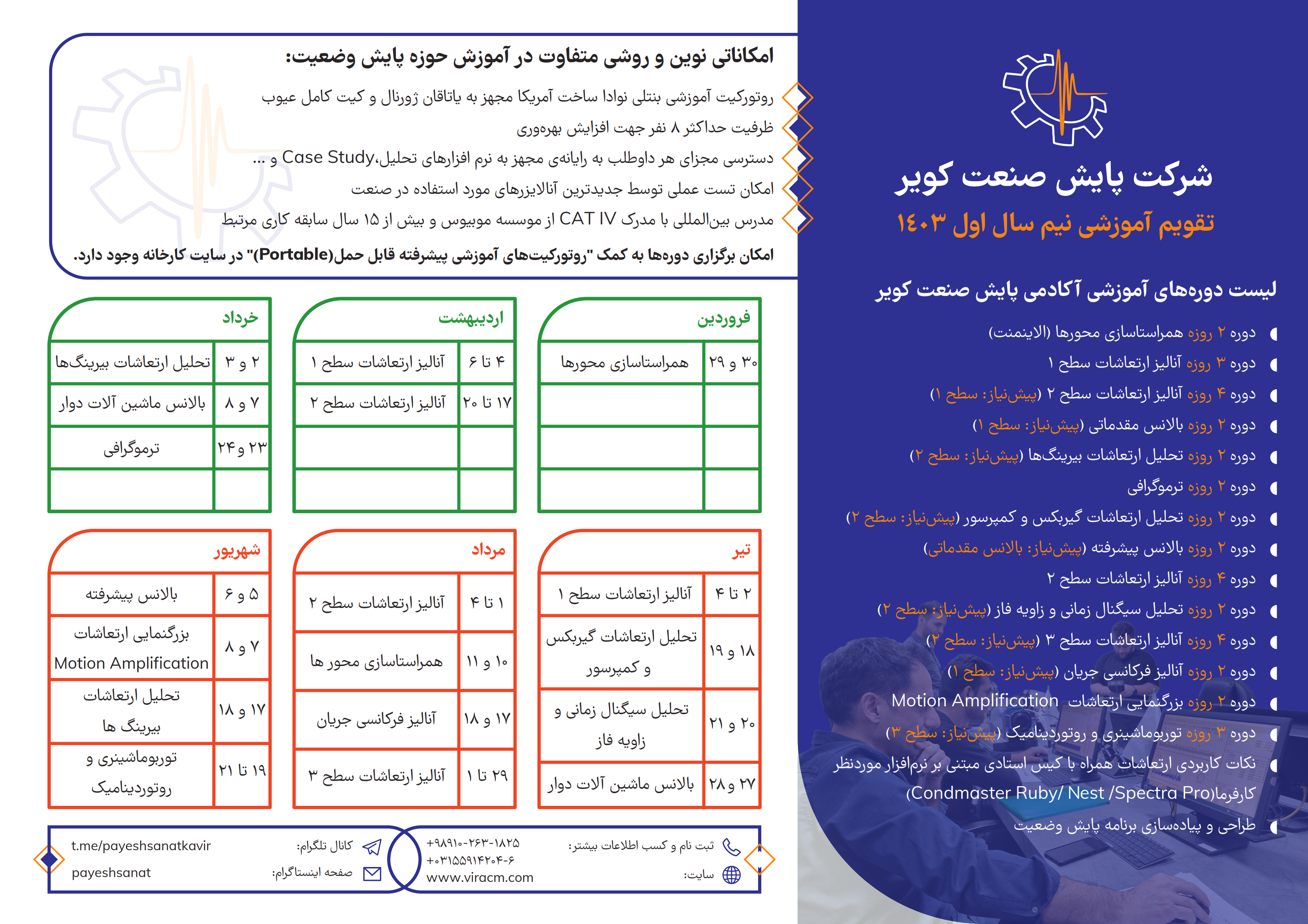
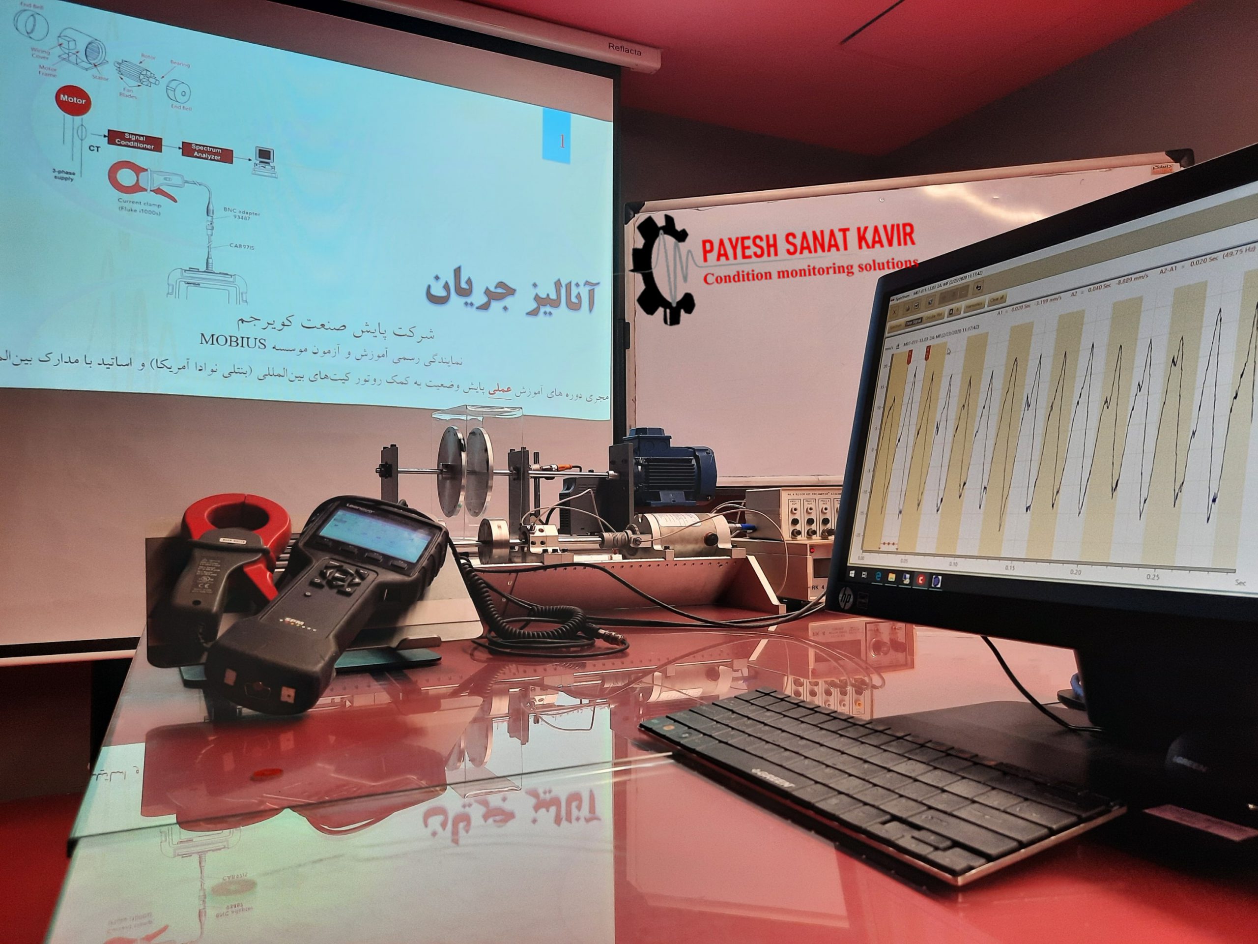
Training with testing AND Analysis
تقویم آموزشی دوره های داخلی
Payesh Sanat Kavir Course Calendar
Register Link for PAYESH SANAT KAVIR Courses
ثبت نام در دورههای پایش صنعت کویر
Training with testing AND Analysis
تقویم آموزشی دوره های داخلی
Payesh Sanat Kavir Course Calendar
In fixed frequency, low voltage, main’s fed induction motors, it is generally accepted that there is normally no pre-warning of insulation degradation. It is normally the case that the insulation degradation in main’s fed, low voltage stator winding cannot be initially diagnosed via online measurements, and the first indication of a problem will be that a fault actually develops.
The concept that the rotor has already developed a fault and will need to be repaired has prevailed; hence, if it is a low voltage induction motor the often the approach is to let it run to failure.
However, in modern production processes any lead-time can be extremely advantageous since unexpected failure of a strategic. Low voltage, induction motor drive can be very costly, and, in some industries, it can be arranged for the motor to be replaced by a healthy one, and the faulty one is send for repair.
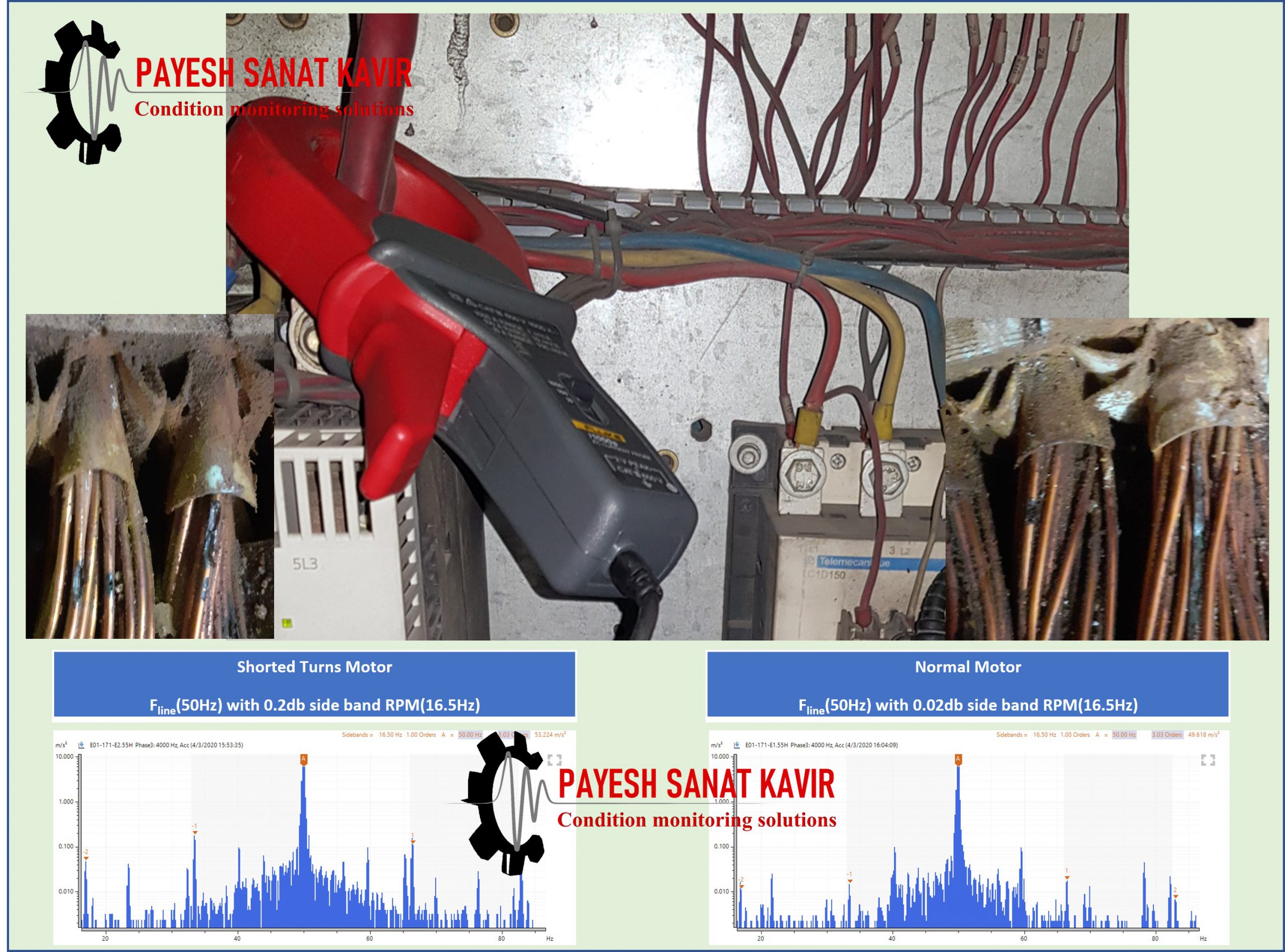
Generally, stator winding-related failures can be divided into five groups: turn-to-turns, coil-tocoil,line-to-line,line-to-ground and open-circuit faults.
Among the five failure modes, turn-toturn faults (stator turn fault) have to be considered the most challenging one since the other types of failures are usually the consequences of turn faults.
The following is an excerpt from William T. Thomson’s book.
The ability to correctly understand the principles of operation of a 3-phase induction motor during normal operation and to correctly apply the basic equations which are required for MCSA testing.
An understanding of the basic construction of large SCIMs.
An understanding of the implications of DOL starts, the torque versus speed curves of the SCIM and its mechanical loads and how to calculate, for example, the run-up time of the motor when driving a mechanical load such as a compressor or pump.
Too many sequential (DOL) starts causing inherent high starting currents,outwith the motor’s design capabilities, Richard Nailen [1.51, 1.52], for example, when the end user does not abide by the original manufacturer’s (OEM’s) specification for the time delays between sequential starts.
Incorrect matching of the motor’s torque–speed curve to the torque–speed curve of the load, so that there is insufficient accelerating torque to cope with all the starting conditions, to which the motor may be subjected by the end user.
The following is an excerpt from William T. Thomson’s book:
Consequently, this book is focused on providing a knowledge source for industrial engineers, who are responsible at various levels for the operation, maintenance, and condition monitoring of induction motors driving strategic mechanical plant.
This book should be of interest to motor manufacturers (OEMs) and electric motor repair shops, since certain end users are now equiring MCSA tests on brand new motors and after repairs to a SCIM to provide base-line current spectra for comparisons with future on-site MCSA measurements.
The OEMs and motor repair workshops should also find MCSA a useful test for their own internal QA/QC checks to estimate the perational condition of a cage winding and operational airgap eccentricity during a full-load heat run. However, this would not be part of a Factory Acceptance Test unless there was a formal contractual agreement to so do.
The following is an excerpt from William T. Thomson’s book:
For further reading, the list of references used is attached at the end of the text.
In the late 1970s to mid-1980s, novel and fundamental research and development work was simultaneously initiated in the United States, United Kingdom, and mainland Europe on the study of current (and spectra) as a function of cage winding breaks in induction motors. In the United States, this work was reported by, for example, Kliman et al. [1.43, 1.44] and in the United Kingdom and mainland Europe various researchers reported on this topic, including, Williamson, [1.45], Vas [1.46], Deleroi [1.47], Hargis et al. [1.48], Tavner [1.49], Filipetti et al. [1.50], and Thomson [1.34].
In 1982, Thomson initiated research into the diagnosis, via MCSA, of unacceptable levels of operational airgap eccentricity in large HV induction motors operating in power stations and offshore oil production platforms and was the first to report an industrial case history in 1986, when an airgap eccentricity problem was diagnosed [1.37].
With advances in digital signal processing, in the late 1970s, it became possible to produce accurate current spectra of the electrical current to the motor and thus diagnose current signatures indicative of cage winding breaks or abnormal levels of airgap eccentricity between the rotor and stator. Both these problems can lead to consequential stator winding and core damage and failures. Although spectrum analyzers and commercially available MCSA instruments can produce current spectra, which present information pertaining to a cage winding break or abnormal airgap eccentricity and are now widely used by industry, it has to be recognized that such instruments are measurement tools to provide current spectra as the initial source of information to be subsequently interpreted as to whether a problem may or may not exist.