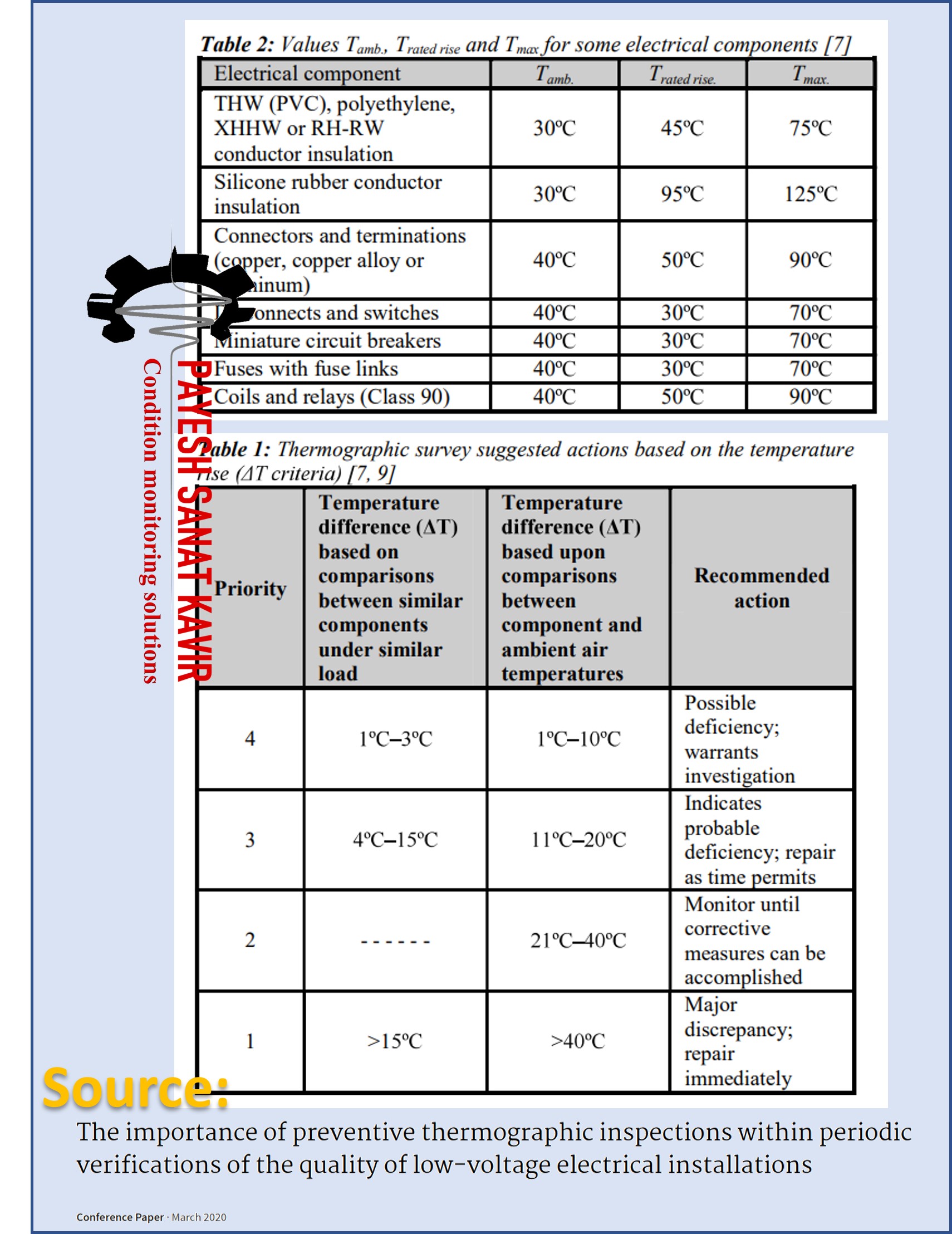
Suggested Actions Based on Temperature Rise
This document has been prepared based on manufacturer instruction bulletins, NFPA, IEEE, NEMA and ANSI standards
Suggested Actions Based on Temperature Rise
This document has been prepared based on manufacturer instruction bulletins, NFPA, IEEE, NEMA and ANSI standards
Guideline VDI 3836 lays down criteria for the evaluation of vibrations in screw compressors and Roots blowers when measurements are taken at the non-rotating and rotating components of these machines in their place of installation. These criteria are also applicable to acceptance measurements of compressor stages carried out in the manufacturer’s test facilities.
As a basic rule, guideline VDI 3836 applies to rigidly or resiliently mounted compressors with outputs as shown in Table 1 of Section 4.1.2, when powered by an electric motor or a steam turbine. In the case of multiple-stage compressors of compact design the evaluation criteria should be applied to each of the stage air ends.
For less powerful machines, application of this guideline can be agreed on between the manufacturer and the customer.
Guideline VDI 3836 does not apply to compressors powered by internal combustion engines. The evaluation criteria presented in guideline VDI 3836 do not apply to the vibrations of the driving machines, which should be evaluated on the basis of the corresponding standards.
Guideline VDI 3836 applies to measurements made on the air ends itself at the measuring positions given in Section 2.3 and under the operating conditions explained in Section 2.6. In the case of measurements of non-rotating parts the evaluation variable is the root-mean-square value of the vibration velocity in two frequency ranges with different upper limits.
Frequency range A covers all major mechanical and flow-related vibration excitations. The additional frequency range B covers only those vibration components with single and doubled rotational frequency of the rotors which usually originate in imbalances. Assessments are given for both ranges in Section 4.
If, in the case of compressors with rotors running on sleeve bearings, the rotor vibrations relative to the bearings are measured, the characteristic variable will be the greatest value of the vibration amplitude (peak-to-peak value S(p-p)) of the vibration displacement.
The assessment criteria mentioned in Section 4 only apply to such vibrations as the compressor generates itself and not to vibrations which are transmitted to the compressor from the driving machine or from external sources. The assessment criteria mentioned in Section 4 are not suitable in the case of compressors for assessing the condition of built-in roller bearings, drive gears, or screw meshing. Information on measuring and assessing structure-borne sound of roller bearings may be found in guideline VDI 3832.
The machines forming the subject of this guideline are subdivided into four groups:
Group 1: Screw compressors with sleeve bearings and timing gears. Screw compressors for process gases normally belong to this group.
Group 2: Screw compressors with roller bearings or roller and sleeve bearings and timing gears. Oil-free air screw compressors will normally be classed with this group.
Group 3: Screw compressors without timing gears. Oil-flooded screw compressors will normally fall in this group.
Group 4: Roots blowers with roller bearings and timing gears
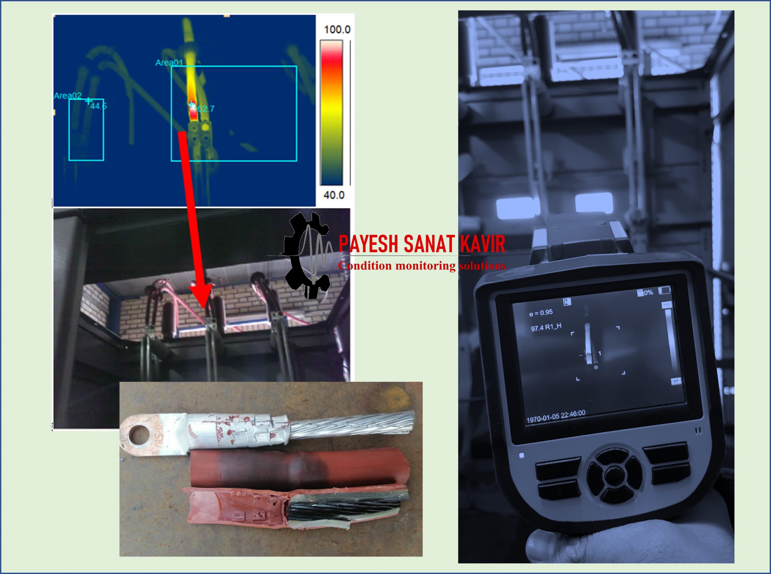
An infrared electrical thermography survey can result in significant financial savings for the client by:
Permissible residual specific unbalance based on balance quality grade G and service speed n
Experimental evaluation
Experimental evaluation of the balance quality requirements is often carried out for mass production applications. Tests are commonly performed in situ. The permissible residual unbalance is determined by introducing various test unbalances successively in each correction plane, based on the most representative
criterion (e.g. vibration, force, noise caused by unbalance).
In two-plane balancing, if no tolerance planes (as specified in 4.4) are used, the different effects of unbalances with the same phase angle and of those 180 apart shall be taken into account.
ISO21940-1